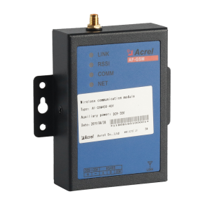
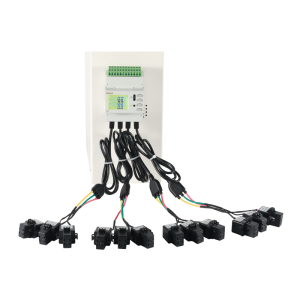
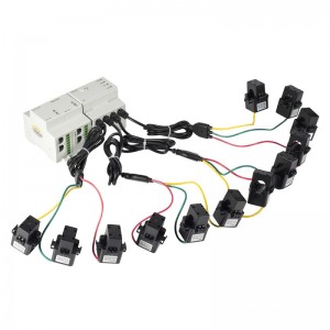
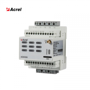
AMC16Z-FAK48 Multi channel din rail ac power meter
AMC16Z series multi channel din rail ac power meter is independently designed to meet the needs of the increasingly high precision power distribution management requirements of the data center. It is suitable for carious all-round inrelligent monitoring of terminal distribution equipment.

* 24 channels of each circuit of A+B
*independent 2 circuits the outgoing current,
*active power, active power, reactive power
*Installation:
DIN rail 35mm
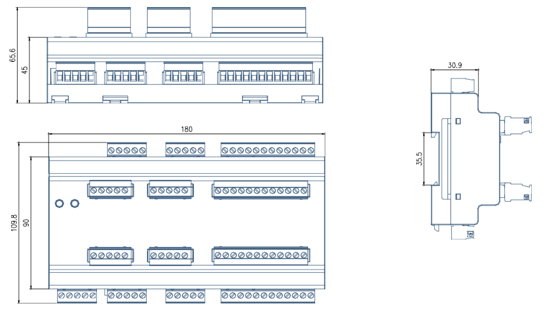
* Dimension(L*W*H):
180*94.3*75mm
Precision power distribution monitoring for data center


|
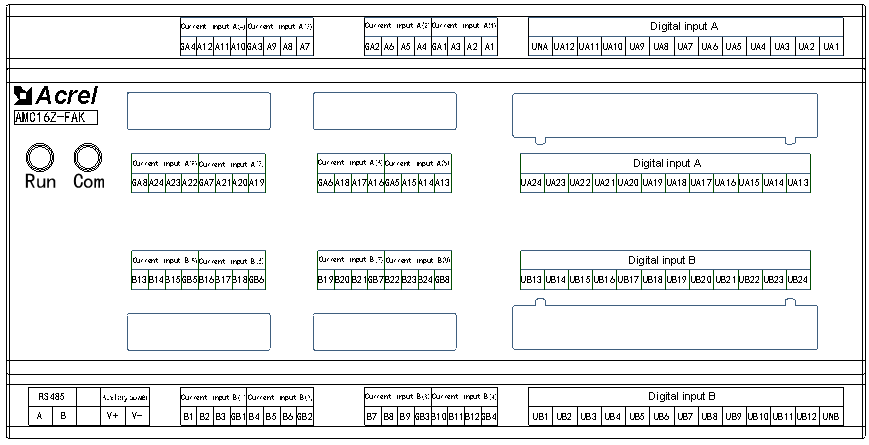
Terminal definition |
Instruction |
Remark |
|
V+ |
Auxiliary power supply |
Power supply by AMC16Z-ZA or powered by DC12-24V |
|
V- |
||
|
A |
RS485 communication |
Connect to touch screen or RS485 hub |
|
B |
||
|
A1 |
A-channel current A phase positive pole(1) |
The first part of A - channel outgoing line three - phase current input |
|
A2 |
A-channel current B phase positive pole(1) |
|
|
A3 |
A-channel current C phase positive pole(1) |
|
|
GA1 |
A-channel current negative common terminal(1) |
|
|
A4 |
A-channel current A phase positive pole(2) |
The second part of A - channel outgoing line three - phase current input |
|
A5 |
A-channel current B phase positive pole(2) |
|
|
A6 |
A-channel current C phase positive pole(2) |
|
|
GA2 |
A-channel current negative common terminal(2) |
|
|
A7 |
A-channel current A phase positive pole(3) |
The third part of A - channel outgoing line three - phase current input |
|
A8 |
A-channel current B phase positive pole(3) |
|
|
A9 |
A-channel current C phase positive pole(3) |
|
|
GA3 |
A-channel current negative common terminal(3) |
|
|
A10 |
A-channel current A phase positive pole(4) |
The fourth part of A - channel outgoing line three - phase current input |
|
A11 |
A-channel current B phase positive pole(4) |
|
|
A12 |
A-channel current C phase positive pole(4) |
|
|
GA4 |
A-channel current negative common terminal(4) |
|
|
A13 |
A-channel current A phase positive pole(5) |
The fifth part of A - channel outgoing line three - phase current input |
|
A14 |
A-channel current B phase positive pole(5) |
|
|
A15 |
A-channel current C phase positive pole(5) |
|
|
GA5 |
A-channel current negative common terminal(5) |
|
|
A16 |
A-channel current A phase positive pole(6) |
The sixth part of A - channel outgoing line three - phase current input |
|
A17 |
A-channel current B phase positive pole(6) |
|
|
A18 |
A-channel current C phase positive pole(6) |
|
|
GA6 |
A-channel current negative common terminal(6) |
|
|
A19 |
A-channel current A phase positive pole(7) |
The seventh part of A - channel outgoing line three - phase current input |
|
A20 |
A-channel current B phase positive pole(7) |
|
|
A21 |
A-channel current C phase positive pole(7) |
|
|
GA7 |
A-channel current negative common terminal(7) |
|
|
A22 |
A-channel current A phase positive pole(8) |
The eighth part of A - channel outgoing line three - phase current input |
|
A23 |
A-channel current B phase positive pole(8) |
|
|
A24 |
A-channel current C phase positive pole(8) |
|
|
GA8 |
A-channel current negative common terminal(8) |
|
|
B1 |
B-channel current A phase positive pole(1) |
The first group B - channel outgoing line three - phase current input |
|
B2 |
B-channel current B phase positive pole(1) |
|
|
B3 |
B-channel current C phase positive pole(1) |
|
|
GB1 |
B-channel current negative common terminal(1) |
|
|
B4 |
B-channel current A phase positive pole(2) |
The second group B - channel outgoing line three - phase current input |
|
B5 |
B-channel current B phase positive pole(2) |
|
|
B6 |
B-channel current C phase positive pole(2) |
|
|
GB2 |
B-channel current negative common terminal(2) |
|
|
B7 |
B-channel current A phase positive pole(3) |
The third group B - channel outgoing line three - phase current input |
|
B8 |
B-channel current B phase positive pole(3) |
|
|
B9 |
B-channel current C phase positive pole(3) |
|
|
GB3 |
B-channel current negative common terminal(3) |
|
|
B10 |
B-channel current A phase positive pole(4) |
The forth group B - channel outgoing line three - phase current input |
|
B11 |
B-channel current B phase positive pole(4) |
|
|
B12 |
B-channel current C phase positive pole(4) |
|
|
GB4 |
B-channel current negative common terminal(4) |
|
|
B13 |
B-channel current A phase positive pole(5) |
The fifth group B - channel outgoing line three - phase current input |
|
B14 |
B-channel current B phase positive pole(5) |
|
|
B15 |
B-channel current C phase positive pole(5) |
|
|
GB5 |
B-channel current negative common terminal(5) |
|
|
B16 |
B-channel current A phase positive pole(6) |
The sixth group B - channel outgoing line three - phase current input |
|
B17 |
B-channel current B phase positive pole(6) |
|
|
B18 |
B-channel current C phase positive pole(6) |
|
|
GB6 |
B-channel current negative common terminal(6) |
|
|
B19 |
B-channel current A phase positive pole(7) |
The seventh group B - channel outgoing line three - phase current input |
|
B20 |
B-channel current B phase positive pole(7) |
|
|
B21 |
B-channel current C phase positive pole(7) |
|
|
GB7 |
B-channel current negative common terminal(7) |
|
|
B22 |
B-channel current A phase positive pole(8) |
The eighth group B - channel outgoing line three - phase current input |
|
B23 |
B-channel current B phase positive pole(8) |
|
|
B24 |
B-channel current C phase positive pole(8) |
|
|
GB8 |
B-channel current negative common terminal(8) |
|
|
KA1 |
A-channel AC voltage A phase (1) |
The first part of A - channel DI |
|
KA2 |
A-channel AC voltage B phase (1) |
|
|
KA3 |
A-channel AC voltage C phase (1) |
|
|
KA4 |
A-channel AC voltage A phase (2) |
|
|
KA5 |
A-channel AC voltage B phase (2) |
|
|
KA6 |
A-channel AC voltage C phase (2) |
|
|
KA7 |
A-channel AC voltage A phase (3) |
|
|
KA8 |
A-channel AC voltage B phase (3) |
|
|
KA9 |
A-channel AC voltage C phase (3) |
|
|
KA10 |
A-channel AC voltage A phase (4) |
|
|
KA11 |
A-channel AC voltage B phase (4) |
|
|
KA12 |
A-channel AC voltage C phase (4) |
|
|
UNA |
A-channel AC voltage null line |
|
|
KA13 |
A-channel AC voltage A phase (5) |
The second part of A - channel DI |
|
KA14 |
A-channel AC voltage B phase (5) |
|
|
KA15 |
A-channel AC voltage C phase (5) |
|
|
KA16 |
A-channel AC voltage A phase (6) |
|
|
KA17 |
A-channel AC voltage B phase (6) |
|
|
KA18 |
A-channel AC voltage C phase (6) |
|
|
KA19 |
A-channel AC voltage A phase (7) |
|
|
KA20 |
A-channel AC voltage B phase (7) |
|
|
KA21 |
A-channel AC voltage C phase (7) |
|
|
KA22 |
A-channel AC voltage A phase (8) |
|
|
KA23 |
A-channel AC voltage B phase (8) |
|
|
KA24 |
A-channel AC voltage C phase (8) |
|
|
KB1 |
B-channel AC voltage A phase (1) |
The first group B- channel DI |
|
KB2 |
B-channel AC voltage B phase (1) |
|
|
KB3 |
B-channel AC voltage C phase (1) |
|
|
KB4 |
B-channel AC voltage A phase (2) |
|
|
KB5 |
B-channel AC voltage B phase (2) |
|
|
KB6 |
B-channel AC voltage C phase (2) |
|
|
KB7 |
B-channel AC voltage A phase (3) |
|
|
KB8 |
B-channel AC voltage B phase (3) |
|
|
KB9 |
B-channel AC voltage C phase (3) |
|
|
KB10 |
B-channel AC voltage A phase (4) |
|
|
KB11 |
B-channel AC voltage B phase (4) |
|
|
KB12 |
B-channel AC voltage C phase (4) |
|
|
UNB |
B-channel AC voltage null line |
|
|
KB13 |
B-channel AC voltage A phase (5) |
The second group B- channel DI |
|
KB14 |
B-channel AC voltage B phase (5) |
|
|
KB15 |
B-channel AC voltage C phase (5) |
|
|
KB16 |
B-channel AC voltage A phase (6) |
|
|
KB17 |
B-channel AC voltage B phase (6) |
|
|
KB18 |
B-channel AC voltage C phase (6) |
|
|
KB19 |
B-channel AC voltage A phase (7) |
|
|
KB20 |
B-channel AC voltage B phase (7) |
|
|
KB21 |
B-channel AC voltage C phase (7) |
|
|
KB22 |
B-channel AC voltage A phase (8) |
|
|
KB23 |
B-channel AC voltage B phase (8) |
|
|
KB24 |
B-channel AC voltage C phase (8) |
1.1 The measurement of the device is not accurate
*Check whether the wiring of voltage and current is correct, and whether the incoming and outgoing lines of current input are correct;
*Check whether the CT setting of the device corresponds to the actual CT used externally;
1.2 The voltage and current are measured correctly, but the power is not measured accurately.
*Check whether the current input direction is correct;
*Check whether the corresponding phase of each current loop is correct;The outgoing circuit shall be adjusted according to actual access.
1.3 Abnormal communication
*Check whether the communication cable is connected normally;
*Check whether the A and B terminals of communication are interlaced;
*Check whether the address of the device is set correctly and the communication baud rate is set correctly;
*When the communication of multiple devices is abnormal, first try whether the single communication is normal;
1.4 There is incoming voltage, current, and power, but electricity has no value.
*Check the CT ratio setting of the incoming line.
1.5 The current of AMC16Z-ZD has a value when the load has no current.
*Adjust the zero value of AMC16Z-ZD current.(the zero point of dc hall sensor is not consistent, the difference is large, need to be adjusted)
Other Question? Please contact us and we will get back to you as soon as possible.
| MINIMUM PAKAGE
|
Package dimensions(1 PC)
220*170*90mm |
Pakage Weight(1 PC)
0.28Kg |
||
| WHOLE BOX PACKAGE | Package dimensions(24 PC)
615*480*395mm |
Pakage Weight(24 PC)
6.72Kg |
||
|
PRODUCT HS CODE
|
9028309000 | |||


